
Generic circuits diagramming tool
I love to draw diagrams and create visual representations of what I do. I think it’s a great way to understand what you plan to do when designing a complex system, to document it for later, and show what you’ve done. Not only targetting others, but first of all for yourself.
Why do I need a generic circuits diagramming tool
In electronics for example, I have the need to draw circuits, representing all the components I’ll use and how they are connected together.
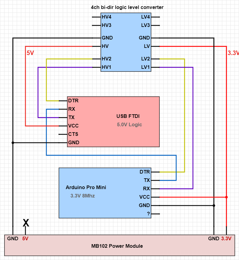
For example, I did this circuit to program a 3.3V Arduino Pro Mini with a 5V FTDI chip using a logic level converter:
Similary, I enjoy designing harware in Verilog HDL, and again, when complexity arise, I need to decompose the components in modules, and represent how they are all connected together.
Here’s a more complex example, my HRM CPU, which is made of a bunch of interconnected components:
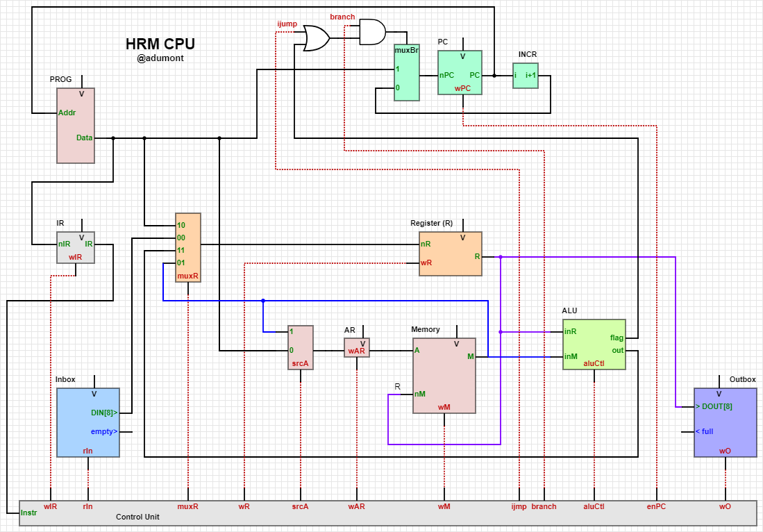
Usually those interconnected modules will have multiple ports (or pins): input/output pins, clock pins, power and ground pins.
There are lots of specialized tools existing that offer libraries with existing components you can select, place on a layout and simply connect together. The problem with those tools is that you depend on the availability of all the components of your design in the existing libraries. Some of those tools also can be extended: advanced users can create new components and publish libraries, but this is out of the scope of what I pretend to do.
Now when we are speaking of designing RTL modules and sub-modules in Verilog, and combining those modules together, you cannot rely on libraries of existing components, because tipically the components you will need will always be custom!
What am I looking for?
So basically what I am looking for is a diagramming tool (free and opensource would be a plus) which would comply with these requirements:
- Allows me to draw custom components
- Allows me to specify pins on each components and name each pins
- Allows me to connect components (by connecting their pins) with “connectors”
- Can save to PNG and SVG
I have no special requirement for it to be fancy or that the diagram look spectacular.
Of course, I expect expensive (licensed) EDA tools from FPGA vendors (Intel, Xillinx,…) to offer this kind of diagramming functionalities, but as an hobbyist, I use primarily free opensource tools, and to date I haven’t found these functionalities in the FPGA free opensource tools space.
What have I found so far?
At work I am using extensively tools like Microsoft Powerpoint and Microsoft Visio. Both are great tools thaht serve their purpose, and which could work fine in this situation, except that I have not found an easy way to comply with Requirement 2.
In Visio you can create your own stencils, but I don’t want to create a new shape for each module I design, plus it’s a pain to do so.
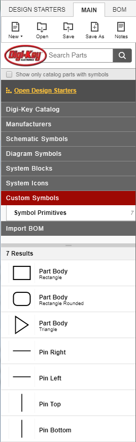
For now, the tool I am using is SchemeIt. It’s a free online tool, provided by DigiKey.
Once in the tool, I don’t use the provided libraries. Instead I use directly the Custom Symbols shapes:
It’s very easy to drag and drop a rectangular shape to create a new empty component, and then drag new pins from the toolbar onto the rectangle!
Look at this quick and dirty example:
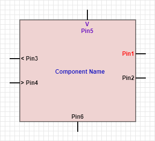
In the layout I have added:
- A rectangular shape for the component
- A name label for the component, which I have colored in blue
- 6 pins, in all directions
- For pins 3 and 4, I have added “<” and “>” to the pin label, which can help indicate input/output pins.
- In pin 5, I have added a “V” in the label to indicate a clock pin.
What I miss in SchemeIt are:
- I haven’t found a way to copy-paste components between different projects.
- No way to rotate components
Alternatives?
- Do you know of better alternatives?
- What do you use to represent your circuits or your designs?
- What do you miss in those tools you use?
Don’t hesitate to join the conversation and leave comments below :).